

Product Application
Contact Us
Telephone:+86-311-83933866
E-mail:jl.dong@mtmems.com
Address:No.1, Meitai Road, Luquan District, Shijiazhuang City
")
Micro-Inertial Measurement Unit (IMU chip)
Contact Us
Product Classification:
Product Introduction
The Micro Inertial Measurement Unit (IMU chip) is a single-device integrated inertial sensor designed for use in automotive applications such as airbag controllers, transmission systems, under-passenger seats, or in the luggage compartment. It features three-axis gyroscopes and three-axis accelerometers. Developed in accordance with the ISO 26262 standard, this IMU is suitable for system applications meeting the ASIL B safety level and can also be used in systems up to ASIL D, fully complying with decomposition rules as well as all necessary requirements and analyses.
Performance metrics
| Spinning top | Accelerometer | System | ||||||
| Measurement range | ±250 to ±2000 | * /s | Measurement range | ±2 to ±16 | g | Supply voltage | 3.3V ± 0.17 | V |
| Scale factor (300°/s) | 100 | LSB/* /s | Scale factor (16g) | 2000 | LSB/g | Operating current | 5 | mA |
| Scale factor nonlinearity (±300° %) | ±0.05 | % | Scale factor nonlinearity (±16g) | ±0.5 | % | Operating temperature range | -40~+125 | Celsius |
| Zero bias | ≤3 | * /s | Zero bias | ≤35 | mg | Shock-resistant | ≥2000 | g |
| Zero-bias instability | 5 | * /h | Zero-bias temperature sensitivity (after temperature compensation) | 2 | mg | Size | 5 × 5 × 1.45 | mm |
| Angular Random Walk | 0.5 | * */h | Zero-bias temperature hysteresis | 0.5 | mg | Weight | To be determined | g |
| Noise (50Hz/400Hz) | 0.1/0.3 | * /s rms | Noise (50Hz/400Hz) | 2/6 | mg RMS | Interface Type | SPI | -- |
| Bandwidth (Filter 1) | 50~400 | Hertz | Bandwidth (Filter 1) | 100~400 | Hertz | |||
| Bandwidth (Filter 2) | 12.5~100 | Hertz | Bandwidth (filter) | 25~100 | Hertz | |||
Application fields
●Level 2 Automated Driving
● Location-based application
● Advanced Driver Assistance Systems (ADAS) features
Main dimensions and interface definitions
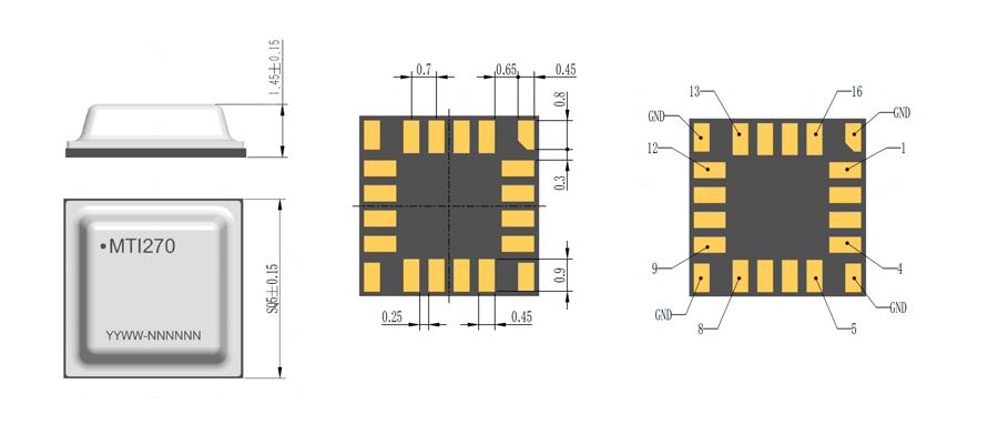
| Pin | Definition | Instructions |
| 1 | CSB | Chip Select Bar |
| 2 | SCK | SPI serial clock |
| 3 | MOSI | SPI serial data input |
| 4 | MISO | SPI serial data output |
| 5 | NC | No Connection |
| 6 | Reset | External Reset Signal, Low Active |
| 7 | BUS_ID_1 | BUS ID1 for Sensor Identification |
| 8 | BUS_ID_0 | BUS ID0 for Sensor Identification |
| 9 | NC | No Connection |
| 10 | NC | No Connection |
| 11 | NC | No Connection |
| 12 | NC | No Connection |
| 13 | GND | Ground |
| 14 | VDD | Power Supply (+3.3V) |
| 15 | DGND | Digital Ground |
| 16 | VDD10 | Chip Digital I/O Supply |
| Note: The NC pin remains floating. | ||
Key words:
Online consultation
If you have any questions about our products and services, please contact us!
recommend products
No relevant data at the moment, please add it backstage!
Contact Phone
Contact Phone
Address
No.1, Meitai Road, Luquan District, Shijiazhuang City